If you’ve learned something here, don’t forget to comment.
Lil about me.
Hi, my names Brad, this blogsite has been going since twenty-sixteen. I started this blogsite as a way to share my passion and quite frankly addition to modifying vehicles to do all sorts of cool stuff.
I’ve had a passion for motorsport since leaving secondary school. To tell a truth, I am focused on speed. Hence my fascination for aerospace.
I pride myself on managing a smart looking site while ensuring its packed full of information in a way that is easy to digest and use. I’m a big believer that if something is aesthetically pleasing people are more likely to read it and make use of that information. Bad presentation kills interest, even if the idea is good.
In twenty-twenty-six I decided to start BlackAngelDevelopments as a company to offer kits to you guys. I found there’s a lot of missed opportunities in these modified communities and I intend to fulfill some of that.
Latest Articles

Resources
If you’re looking some communities to discover, learn and build your car then I strongly suggest you check out the following pages, communities and YouTube channels. I have no personal affiliation with them but, I’m often using them as a resource myself.
What to check out next?
If you’re interested in articles about my turbocharged MX-5 then I you can click here. Alternatively if you came here to read about my Navara then you can click here.
What you want more?
Okay, check out other users builds by clicking here. Or if you just want to read articles by other users ranging from reviews, to tutorials then click here.
Generic MX5
D40 Navara
Generic Boosted MX5
D40 Tuning
Frequently Asked Questions
I’m looking at making my own blog should I?
Absolutely. If you as passionate as me about sharing knowledge for free on the internet then without a doubt. If anyone needs help crating their own blogsite for their latest project or interest drop me a message and I can help you with hosting and management.
Why don’t I do YouTube?
I realize many people prefer to pop open a beer and sit back and watch a video compared to a blog format. However I personally find it very difficult to articulate important parts within a video format. I do find that reading a well written article is far more packed with information that otherwise wouldn’t be conveyed.
I’d like to share something I’ve done but I don’t have time to make my own website. Can you help?
Certainly. I’ve got two areas on my blogsite. Your articles, for helpful guides, reviews etc that you wish to share to your mates. Your Builds, to share your entire cars build from suspension parts to engine management and everything in-between. Got that friend who’s always asking what parts you run? Drop me a message and lets make you an article that you can share and give your car some spotlight it deserves.
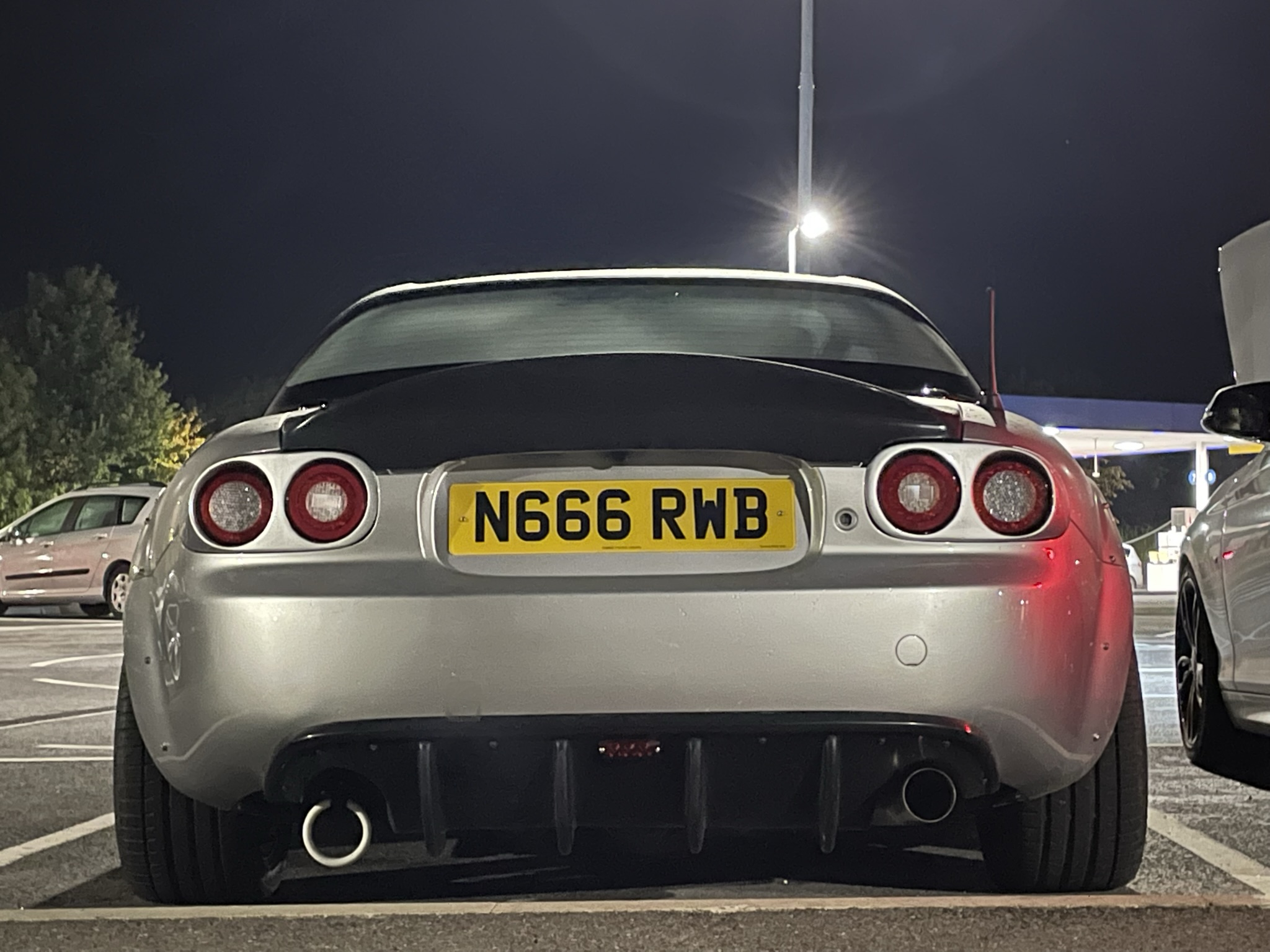
Is RWB and BAD run by the same guy?
Yeah, actually they are. RWB is my blogsite and BAD is my e-commerce outlet.